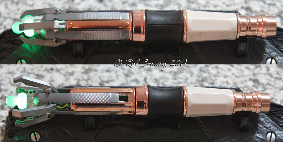
If you bought the first edition of the Wand Company's 11th Doctor remote control sonic screwdriver, you're probably pretty disappointed it doesn't extend like in the show (the new one does). Fortunately I was too, so took it apart and figured out how to make it happen anyway. It now does and still has all the sound and remote control functionality, and doesn't require purchase of the Dr. Who sonic screwdriver toy version for parts. The only extra parts required are 4 sets of: 2mm hex nut and screw & <3mm dia compression spring. I'd say this process is a little precarious so best for seasoned crafters. It's best to read through the whole thing to see if it's something you want to attempt.
What it looks like:
How to get there:
A) Knock out pins to release the 4 claws at the tip
B) Unscrew the locking ring and tiny screws at the base
C) Unscrew the long screw holding the metal tips together
D) Mark on the black plastic where the holes from the copper shroud line up (you'll need to cut a hole there later and want it to line up)
E&F) Pop open the black plastic case to gently remove the electronics (remove tape at E & pop open clip at F). Don't loose springs at F.
Now comes the tricky bit. Cutout all the sections G - K as follows:
G) Cut the cross bar on the copper shroud to make the long slot longer - all 4 locations. Smooth the edges and top so the metal tip can smoothly slide past where the bar used to be. Don't smooth too far up, you don't want the metal tip to slide very far, just a cm or so.
H) Trim the metal tip right to the claw holders so the claws can tilt - all 4 locations. (see L instructions too)
I & J) Remove and smooth down the claw pins - all 4 locations.
K) Cut the remote wires at the left side of the blue rectangle and the black plastic at the right side of the blue rectangle.
L & M) Trim pin hole (M). Trim base of 4 claws near pivot hole and towards back (L) to allow them to swing up (see H also). Test with tiny wire/pin/screw holding claws in place to see if you need to trim more to get it to move to the angle you want. You only need the metal tip and copper shroud, not the black plastic, electronics or green tip.
Copper shroud trimmed enough so metal tip slides. Metal tip not trimmed enough yet for claws, but ready to add claws to test:
Testing angle (green tip and black plastic not required at this step):
N) Trim ends of metal tip so they're less likely to hit any of the electronics - 4 locations. With the electronics safely removed, trim the black plastic where you marked the holes. You'll need to trim wider than that to let the metal tip through though. Test with metal tip and copper shroud over top until you can now slide the metal tip even with the black plastic in place (see previous picture).
O) Drill claw pivot hole larger to accommodate 2mm screw. Use the same drill to widen the metal tip claw holders to accommodate the screws too. Assemble the claws onto the metal tip and recheck/adjust trimming for proper claw tilt angle with the larger holes. Epoxy spring into claw just beyond screws & pivot point. For springs, I used CBC-0340-0015-S from Custom Springs Manufacturer | Wire Forms | Stock Springs. Their minimum order qty was $25+ship so if you find similar elsewhere, likely worth a try. I have a few sets of leftovers to sell at cost if folks are interested. If anything different, I'd go for a slightly heavier spring/slightly longer, rather than lighter/shorter.
P) Solder thinnest flexible (braided) wire you can find, to extend the IR tip about 4cm. Cover solder joints with liquid electrical tape (paintable insulator).
Put it all back together - without glue first to check fit, then with glue for final assembly:
- insert electronics in black pastic.
- close plastic (start the LED wires in a spiral so the wires will become a spring inside the metal tip cavity). Lightly glue plastic shut if needed.
- insert black plastic in copper shroud (you should glue this one in place when you've tested everything and you're ready for your final assembly.
I'd recommend silicone glue in case you ever need to remove it, and just at the end near the battery) - add the metal tips to the copper assembly. Ensure the wires keep spiraling in the metal cavity. Tuck excess wire back into the black plastic cavity, or recut/resolder to better length. Glue side of IR LED to green plastic tip so it doesn't wander. You can also glue the green tip to one side of the metal tip if you want to. Close the metal tip with the long screw, ensuring you're not pinching wires anywhere. Add claws with 2mm screws and nuts. Leave nuts a little loose and glue them in place to ensure no interference with claw motion.
For the final look - go back to the top image.
 All images copyright Rob Emery